- SOLARWATT Manager
- Commissioning
- Interfaces and technical data
Interfaces and technical data
Overview of interfaces and technical data of the SOLARWATT Manager devices.
Table of contents
SOLARWATT Manager flex 1.5
Interfaces
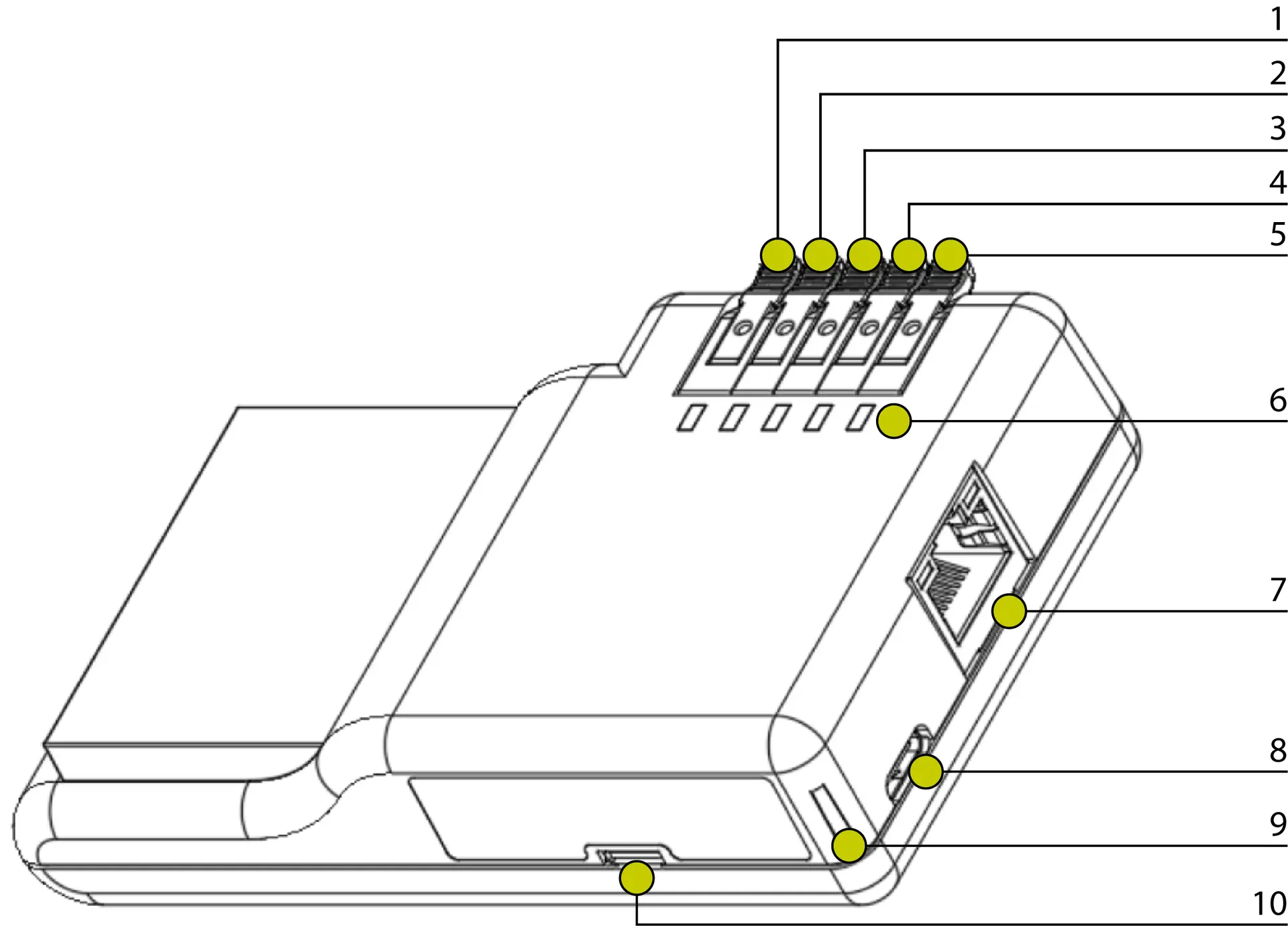
| Connection | Function | |
|---|---|---|
| 1 | Clamp Terminal | not in use |
| 2 | Clamp Terminal | not in use |
| 3 | Clamp Terminal | Ground |
| 4 | Clamp Terminal | S0+, S0 supply voltage |
| 5 | Clamp Terminal | S0–, S0 impulse input |
| 6 | Status-LEDs 1–5 | Signals for device operation |
| 7 | RJ-45 | Ethernet, 10/100 MBit |
| 8 | USB-C | Power supply |
| 9 | Power LED | Signal for power supply and operating state |
| 10 | Micro-USB | USB-2.0-Host |
Technical Data
| Supply voltage | 5 V |
| Min. power consumption | 2 W |
| Max. power consumption | 10 W |
| Ambient temperature | 0 °C ... +50 °C (+32 °F ... +122 °F) |
| Relative humidity | 15 % ... 85 % RH |
| Housing material | Plastic (ABS) |
| Dimensions (W × H × D) | 65 mm × 24 mm × 102 mm (2.56 in × 0.95 in × 4.02 in) |
| Weight | 88 g (0.2 lb) |
| Mounting options | Recommended: wall mounting with provided screws Alternative: with adhesive pad or magnets on suitable surface |
| Degree of protection | IP 20 |
| Conformity | RoHS, CE |
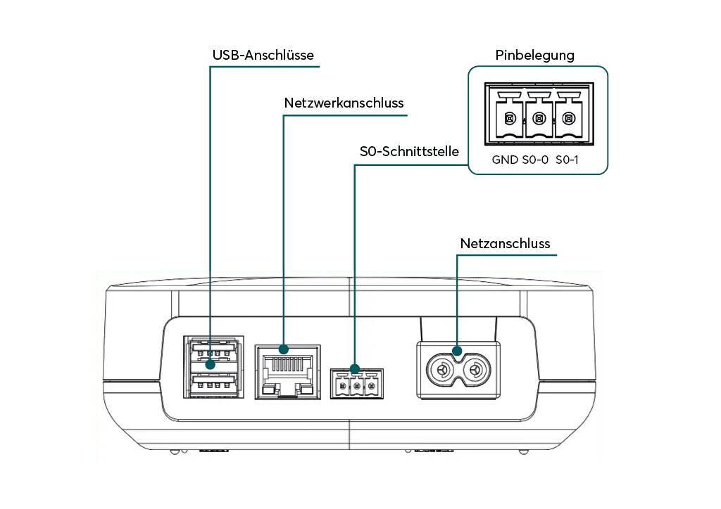
SOLARWATT Manager flex 1.0
Technical data
| General data | |
|---|---|
| Device supply | internal universal power supply 120-240 V; 50/60 Hz |
| Power input | nom. 3 W; max. 12 W |
| Ambient temperature | -10 °C to +50 °C |
| Housing | Composite |
| Dimensions (W x H x D) | 130 x 130 x 40 mm |
| Installation type | Wall installation |
| IP rating | IP20 |
| I/O interfaces and connectable devices | |
|---|---|
| Ethernet (LAN) | 1x RJ-45 10/100 MBit |
| PLC | AV Home Green Phy |
| Clamp connection | 2x S0/Digital In |
| USB | 2x USB 2.0 host, USB socket type A |
| Device software | |
|---|---|
| Operating system | Linux, Kernel 7.x |
| Communication platform | SOLARWATT Manager portal (Cloud) |
| Security | VPN tunnel according to IPSec standard, secure protocols (SSH/SSL, SFTP, HTTPS) |
| Firmware and app updates | via update server |
| Languages | german, English, French, Italian, Dutch, Spanish, Swedish |
| SOLARWATT Manager portal | |
|---|---|
| Supported media | Desktop PC, tablets, smartphones |
| Supported browsers | Google Chrome, Mozilla Firefox, MS IExplorer, Apple Safari |
| Security | VPN tunnel according to IPSec standard, secure protocols (SSH/SSL, SFTP, HTTPS) |
| Languages | German, English, French, Italian, Dutch, Spanish, Swedish |
EnergyManager pro
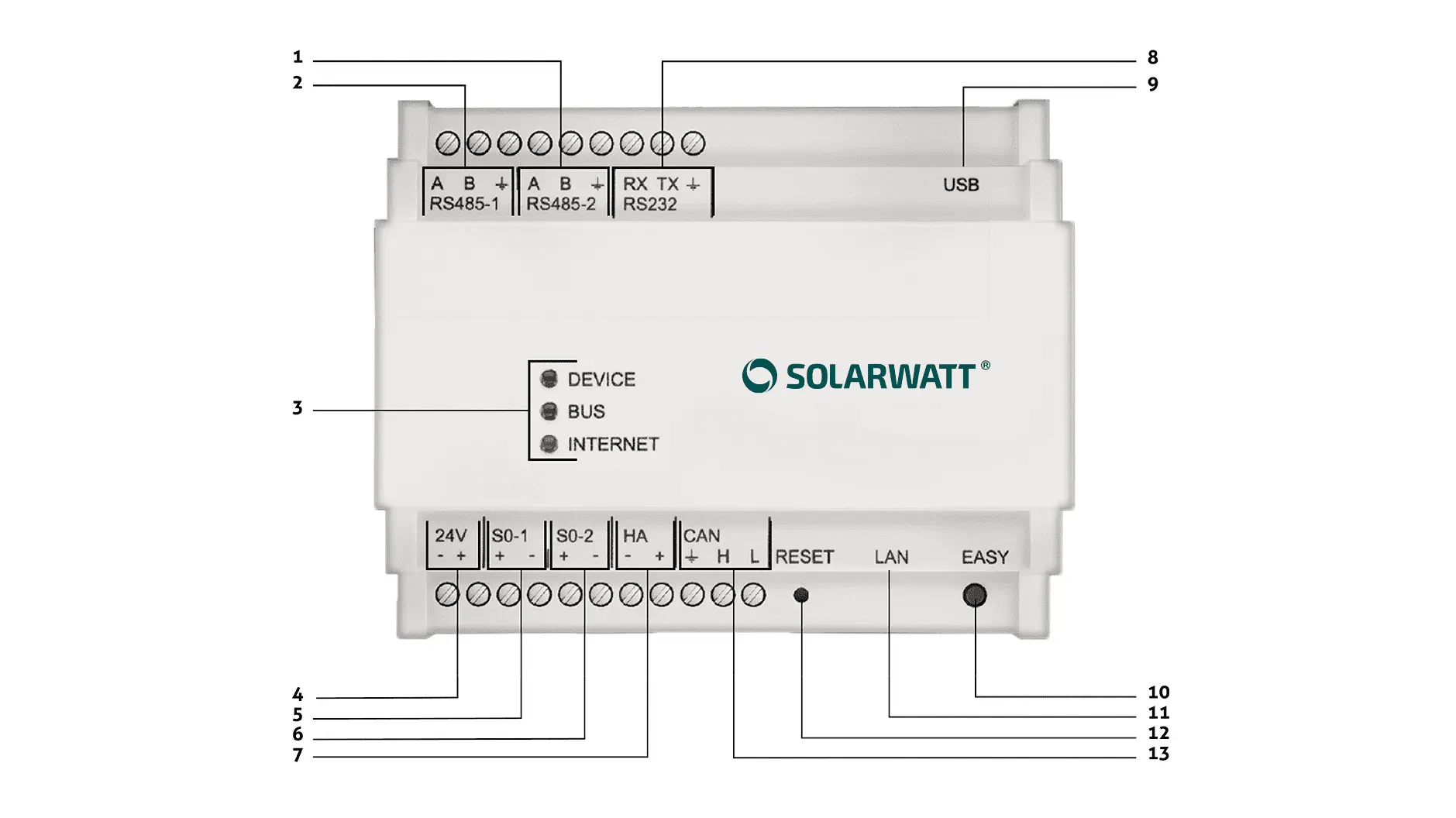
Overview of LEDs, buttons, interfaces
| 1 | RS485 connection sockets, 2 | 8 | RS232 connection sockets |
| 2 | RS485 connection sockets, 1 | 9 | USB connection sockets, 2 x |
| 3 | LEDs | 10 | EASY button |
| 4 | 24 V connection sockets | 11 | LAN connection socket |
| 5 | S0 connection sockets, 1 | 12 | RESET button |
| 6 | S0 connection sockets, 2 | 13 | CAN connection sockets |
I/O interfaces and connectable devices
| Ethernet (LAN) | 1x RJ-45 10/100 MBit | |
|---|---|---|
Terminal connection
| 2x RS485 | 10 devices per interface |
| 2x S0/Digital In | 1 device per interface | |
| 1x CAN | AC-Sensor | |
| USB PORT | Serial number ERCxx-xxxxxxxxx: 2x USB 2.0 device, USB socket type A Serial number ERKxx-xxxxxxxxx, ERZxx-xxxxxxxxx: 1x USB 2.0 device, USB socket type A | |
| Digital extension | Serial number ERCxx-xxxxxxxxxxx: max. 5 Digital Extensions Serial number ERKxx-xxxxxxxxx: max. 5 Digital Extension Serial number ERZxxxx-xxxxxxxxx: no Digital Extension |
Technical data
| Power supply | via external top-hat rail power supply (230 V AC/24 V DC; 1.5 A; 3 TE) |
|---|---|
| Power input | 2.4 W (without extensions) |
| Ambient temperature | -10 °C to +40 °C |
| Housing | Composite |
| Dimensions (W*H*D) | 108*90*70 mm, 6 TE (horizontal pitch) |
| Installation type | TS 35 top-hat rail |
| IP rating | IP20 |
Device software
| Operating system | Linux, Kernel 2.6 |
|---|---|
| Communication platform | SOLARWATT Manager portal (Cloud) |
| Security | VPN tunnel according to IPSec standard, secure protocols (SSH/SSL, SFTP, HTTPS) |
| Firmware and App updates | via update server |
| Language: German | German, English, French, Italian, Dutch, Spanish, Swedish |
Manager portal and applications
| Supported media | Desktop PC, tablets, smartphones |
|---|---|
| Supported browsers | Google Chrome, Mozilla Firefox, MS IExplorer, Apple Safari |
| Security | VPN tunnel according to IPSec standard, secure protocols (SSH/SSL, SFTP, HTTPS) |
| Languages | German, English, French, Italian, Dutch, Spanish, Swedish |
Functions
| Max. Number of extensions | 20 (theoretical number supported by the software. Maximum extension bus supply power of the EnergyManager 5 V: 10 W, 24 V: 24 W. The actual maximum number of extensions is calculated from the sum of the respective supply power of the connected extensions. These can be found in the respective data sheet) |
|---|---|
| Interface management | Clear management of all interfaces and configuration of the devices via local website in the LAN |
| Device management and installation | Installing, uninstalling, managing devices via website, EASY-Install for automatic detection of devices |
| Type of manageable devices | Smart home systems, PV systems/inverters, CHP units, heat pumps, battery storage systems |
| Applications | Management of various applications for measuring, controlling and automating energy flows |
Technical data Digital Extension
Connections
| Connection | Quantity | Intended use |
|---|---|---|
| Digital In | 6 | Universal pulse input for pulse counter |
| Digital Out | 6 | 24 V DC switchable universal output for connecting coupling relays or SG Ready heat pumps |
optional/currently not provided:
| Connection | Quantity | Intended use |
|---|---|---|
| U Out | 2 | 24 V DC non-switchable universal output that taps supply voltages, e.g. for ripple controllers |
| 24 V | 1 | Additional 24 V DC auxiliary supply input |
LED status
| Status LED | Device | Bus | I/O |
|---|---|---|---|
| Off | No voltage | No connection to the extension bus | - |
| Green | In operation, extension is being used by the EnergyManager | Bus connection OK | Signal input/output |
| Orange | In operation, extension has not yet been assigned a driver in the EnergyManager | - | - |
| Red | - | - | - |
The I/O LED only flashes when there is an actual signal input or output. If several signals occur within 200 ms, the LED only flashes once.
When the DIGITAL extension is connected for the first time, the device LED lights up orange. The Extension DIGITAL is in operation and can be used by the EnergyManager. The interfaces of the DIGITAL extension appear under Interfaces/Drivers. As soon as at least one driver is assigned there, the LED lights up green.